Lithium-ion (Li-ion) batteries play a crucial role in various applications, including energy storage and electric vehicles. However, they are prone to cell voltage imbalance over time, which can significantly reduce battery capacity and overall performance. To address this issue and improve the lifetime of battery packs, cell balancing methods have been developed. These methods can be broadly categorized into four types: passive cell balancing, active cell balancing using capacitors, Lossless Balancing, and Redox Shuttle. Each Cell Balancing Technique approaches cell voltage and state of charge (SOC) equalization differently. Dig into the types of Battery balancing methods and learn their comparison!
Importance of Li-ION BATTERY CELL Balancing
Cell imbalance is a significant concern in large battery packs, leading to performance degradation and safety issues. Passive and active cell balancing are two battery balancing methods used to address this issue based on the battery’s state of charge (SOC). To illustrate this, let’s take the example of a battery pack with four cells connected in series, namely Cell 1, Cell 2, Cell 3, and Cell 4. Before balancing, the SOC level of cells L1,L2,L3, and L4 were 40%, 60%, 80%, and 100%, respectively. The passive cell balancing method achieves SOC (state of charge) equalization by dissipating energy from cells with higher SOC, thereby aligning all cells to a similar SOC level comparable to the lowest cell SOC, which is specifically 40% of the SOC level L1 in Cell 2. This process can be visualized in the illustration below.
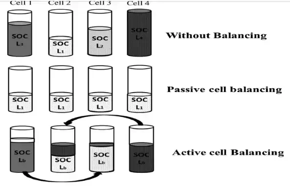
Likewise, the active cell balancing transfers the energy from the highest SOC cell 4 (SOC L4 of 100%) to the lowest SOC cell 2 (SOC L1 of 40%) and SOC of cell 1 (SOC L3 of 80%) into SOC of cell 3 (SOC L2 of 60%), hence all the cells SOC level will be equal to 70% (SOC Lb). This battery pack balancing method is suitable for nickel and lead-acid batteries, as it avoids overcharge damage, and is cost-effective, but may result in energy losses due to dissipation as heat during balancing.
Passive cell balancing
This battery balancing method uses resistors in a balancing circuit that equalizes the voltage of each cell by the dissipation of energy from higher cell voltage and formulates the entire cell voltages equivalent to the lowest cell voltage. This technique can be classified as a fixed shunt resistor and switching shunt resistor method. Also, this method should be used when charging mode only. Because discharge mode does not have reverse direction switching which results in a higher aggregated imbalance in each cycle.
Types of Passive Cell Balancing Techniques
- Fixed shunt resistor method
The fixed shunt resistor cell balancing circuit, shown in the picture below, utilizes fixed shunt resistors (R1, R2, R3, R4, … Rn) connected in parallel with each series connected cell (V1, V2, V3, V4, … Vn) to balance each cell’s voltage. In this technique, the balancing current is effectively dispersed through the resistor, which in turn controls the voltage of each cell.
It is worth noting that this method is particularly well-suited for nickel and lead-acid battery balancing circuits. These battery types are capable of handling overcharge conditions without incurring any damage.

- Switching shunt resistor method
The switching shunt resistor cell balancing circuit, shown in the picture below, uses semiconductor switches (Q1, Q2, Q3, Q4, … Qn) and fixed shunt resistors (R1, R2, R3, R4, … Rn) to balance each cell’s voltage. In this circuit, each series-connected cell is linked to the resistor in parallel through controlled on/off switches or relays. The value of the resistor is carefully selected to match the required balancing current. A controller operates the circuit in two modes: continuous mode, where the switches are controlled simultaneously, and sensing mode, where a voltage sensor detects cell imbalances and decides which resistor should be shunted.
This technique, often referred to as “charge shutting,” is a popular battery balancing method for balancing Li-ion batteries. It offers increased reliability compared to the fixed shunt resistor approach. However, it’s essential to be aware that this passive cell balancing algorithm may result in some energy losses as higher currents flow through the switches and resistors during the balancing process.

Comparison of passive battery balancing methods
| Type | Balancing principle | Merits | Demerits | Applications |
| Fixed shunt resistors | Cells with higher energy levels are dissipated through parallel resistors as heat until charge levels match with cells of lower energy level | Low cost, easy to implement | Permanent energy losses, no controlled operation | Suitable for nickel and lead-acid batteries low power applications |
| Switched shunt resistors | Cells with higher energy levels are dissipated by switch control that decides which resistor should be shunted for energy balance | A simple controlled method based on SOC and SOH, Easy to implement | Energy losses due to high balance current, slow balancing speed, more number of switches, preferable during charging only | Suitable for Li-ion battery Low power applications such as consumer appliances, suitable for electric vehicles when10 mA/Ah balancing current is used |
Hence, these two battery balancing methods can be executed for low-power applications, with a balance current lesser than 10 mA per Ah capacity of the cell. The general comparison among passive cell balancing methodologies proposed in this article is listed in the Table above.
ACTIVE CELL BALANCINGTECHNIQUE
This method is known as a non-dissipative balancing technique that uses storage elements such as capacitors or inductors which transfer the energy from a higher charge cell to a lower charge cell until all the cells are balanced. This method can be classified based on capacitors, inductors, and power electronic converters. Also, this method can be used in both charging and discharging operations. This balancing circuit balances the cells in a shorter time and high efficiency than the passive balancing technique. But this circuit is a very complex system which increases the system cost high.
Types of Active Cell Balancing Methods
- Capacitor-Based Active Balancing Method
In the capacitor-based active balancing method, capacitors act as external energy storage devices to facilitate the transfer of energy between cells, thereby balancing their state of charge (SOC).

- Switched Capacitor
Switched capacitor methods equalize energy between two neighboring cells using switched capacitors. This technique is easier to control and implement and is suitable for both charging and discharging operations. However, it may require a longer balancing time for end-to-end cell equalization, especially in large battery packs with multiple cells.
- Single Switched Capacitor
This approach is often referred to as the “charge transfer method,” involving the release of charge from a cell with higher SOC. This charge is then stored in a capacitor before being transferred to a cell with lower SOC. The key advantage of this technique lies in its simplicity, as it only requires the use of one capacitor to balance the entire battery pack. However, it requires intelligent control techniques and multiple switches to regulate the flow of energy. Furthermore, the balancing speed is relatively slower compared to other capacitor-based methods.
- Double Tiered Switched Capacitor
This approach involves energy equalization between two adjacent cells through the first row of capacitors and non-adjacent cells through the second row of capacitors. The implementation of the double-tiered configuration significantly reduces the balancing time, surpassing the time required by more than half when compared to the switched capacitor method. While this technique provides faster balancing, it also requires a higher number of capacitors.
- Inductor-based battery balancing methods
The inductor-based cell balancing circuit achieves cell balancing by utilizing magnetic elements like inductors or transformers. These elements carry unequal energy among multiple cells, conveying unbalanced cell energy from higher energy cells to lower energy cells in the battery pack.
- Single/Multi Inductor
In this cell equalizing circuit employing single or multiple inductors, the controller algorithm detects the voltage of each cell and determines the appropriate cell to transfer power. When the MOSFETs are switched on and off, unbalanced cell energy is directed to an inductor. While this inductive cell balancing technique offers fast balancing and good efficiency, it comes with a higher manufacturing cost and requires complex control systems. Moreover, considering the high switching frequency, it is necessary to equip each cell in the battery line with a filtering capacitor.
- Single Transformer
An active cell balancing circuitry utilizing a single transformer method comprises components such as a MOSFET, a diode (D), a transformer (T), N+2 switches (S1~SN+2), and N battery cells (B1 ~ BN). This cell balancing system with a single transformer can be implemented with two distinct topologies: pack-to-cell and cell-to-pack methods. The first topology transfers energy from the pack to the cells, while the second transfers energy from the cells to the pack. The single transformer method offers fast balancing with minimal losses. However, it requires accurate switch control and may need to change the magnetic core if cells are added or removed.
- Multiple winding transformers
This method utilizes multiple transformers to balance the energy between cells. To implement this method, you would need n cells (B1 – BN), diodes (D1 – DN), transformers (T1 – TN), and a single MOSFET. The control mechanism is straightforward, as the inductor identifies the cells’ voltage and decides which cells to transfer power to. While it offers fast balancing and better modular design, it also requires a costly and complicated circuit and may lead to transformer saturation.
- Active Balancing Based on Converters
Converter-based cell balancing uses various types of converters, such as Buck-Boost and Cúk Converters, to balance unequal cells. These converters offer superior energy efficiency, making them well-suited for medium to high-power applications. However, they require complex control algorithms and additional passive components and active switches, leading to a higher cost and larger size.

- Buck-Boost Converter
Buck-Boost converters find widespread application in Battery Management Systems for cell balancing purposes. They efficiently dissipate excess energy from cells with higher SOC to a separate battery system and then transfer the energy back to cells with lower SOC. While this topology offers high energy efficiency and modular design, it requires intelligent controllers and voltage-sensing devices for its operation.
- Cúk Converter
The Cúk converter is a type of buck-boost converter known for producing zero ripple current. It operates by utilizing a single switching device and a mutual capacitor to interconnect the power or energy. While it offers advantages like zero ripple current, it may also require additional circuitry to achieve the desired balancing results.
- Flyback Converter
Flyback converters find application in isolated structures and can be either unidirectional or bidirectional. During charging, the linked switch stores the highly charged cell’s energy in the transformer, and when switched off, it transfers the energy to the pack. The bidirectional flyback converter offers enhanced energy transmission flexibility, as it can transmit energy not only from the cells to the pack but also from the pack back to the cells. However, this method may have disadvantages like magnetic losses and the homogeneity of multi-windings.
- Ramp Converter
The ramp converter cell balancing topology shares similarities with multi-winding transformers. Unlike the conventional method of having one secondary winding per cell, the ramp converter simplifies the process by requiring only one secondary winding for each pair of cells. The operation of the ramp converter involves directing most of the current to charge the odd-numbered lowest voltage cells during the first half-cycle, while the even cells are supplied with current during the other half-cycle. Due to this behavior, it is called the ramp converter. While it provides a fast balancing speed, it still requires more components and may lead to higher costs.
- Full-Bridge Converter
Full-bridge PWM energy converters serve versatile purposes as both AC-DC converters and DC-DC converters, making them well-suited for plug-in hybrid electric vehicles (PHEV) and energy storage systems. These applications demand intelligent control and are highly advantageous for modulated battery packs and high power ratings. Nevertheless, it is essential to acknowledge that the full-bridge converter’s drawbacks encompass relatively higher costs and complex control requirements.
- Quasi-Resonant Converter
The Quasi-Resonant Zero Current Switching (QRZCS) balancer represents a DC-DC converter-based cell balancing solution. It has similarities to the buck-boost topology but includes the addition of a resonant circuit. The QRZCS balancer offers benefits like large energy efficiency, but it is also the most complicated equalizer due to its extensive number of components and intricate operation.
Comparison of Active Cell Balancing Methods
Based on Different Cell Balancing Techniques
| Techniques | Advantages | Limitations | Applications |
| Capacitor-Based | Fast balancing, high efficiency | More switches, complex control, slower balancing speed | High-power applications like EVs and energy storage |
| Inductor-Based | Fast balancing, good efficiency | High manufacturing costs, complex control, and filtering needed | High-power applications need precise voltage sensing |
| Converter-Based | High energy efficiency, modular design | Complex control, higher cost, larger size | Medium to high-power applications, modular designs |
Based on Different types of active cell balancing algorithms
| Types | Balancing principle | Merits | Demerits | Applications |
| Single capacitor | Transfer of energy from cell with higher energy level into lower energy cell through only one capacitor | Control with only one capacitor, preferable during both charge and discharge. | More number of switches, intelligent control technique, adequate balancing speed | High power applications such as uninterruptible power sources, energy storage systems, hybrid electric vehicle and electric vehicles |
| Switched capacitors | Energy equalization between two neighboring cells through switched capacitor | Easy to control and implement, low voltage stress, preferably during both charge and discharge | Long balancing time required for end-to-end cell equalization | |
| Double-tiered switched capacitors | Energy equalization between two adjacent cells through the first row of capacitor and nonadjacent cells through the second row of the capacitor | Balancing time can be reduced to more than half compared with the switched capacitor, preferable during charge and discharge condition | Adequate balancing speed, more capacitors | |
| Single inductor | Transfer of energy from cell with higher energy level into lower energy cell through only one inductor | Fast balancing speed than single capacitor, higher efficiency | High system cost, more number of switches, intelligent control technique, filter the capacitor is required due to the high switching frequency | |
| Several inductors | Energy equalization between two adjacent cells through switched inductor | Fast balancing time, high efficiency | High system cost, complex control of end-to-end cells, the filter capacitor is required due to high switching frequency | |
| Single transformer | Pack to cell equalization and cell to pack equalization through single transformer | Fast balancing speed, low magnetic losses | High system cost, requires perfect electronic switch control, the magnetic core must be changed if one or more cells are added | |
| Single magnetic core transformer | Pack to cell equalization and cell to pack equalization through single core multiple secondary winding transformer | Rapid balancing with minimal losses, no closed-loop control | Very high system cost, complex control, the magnetic core must be changed if one or more cells are added | |
| Multiple magnetic core transformers | Energy balance of each cell through individual multi winding transformers | Fast balancing speed, better modular design, new cells added easily without change of magnetic core | Most expensive, complex circuit, high transformer magnetic losses |
Comparisons between battery balancing methods are provided in the tables above. Switching shunt resistors are suitable for low-power applications due to their low cost, small size, and easy control. Switching capacitors offer simple, active control and are ideal for EV applications but require fast equalization time. Switching inductors and transformers are suitable but involve complex control systems and may result in magnetic losses. Superior energy converters provide complete control for medium and high-power applications, but they come with higher costs and complexity. The right method should be chosen based on specific application needs.
Other two Battery Balancing Methods
Lossless balancing
Lossless balancing is an innovative approach that minimizes hardware components by employing advanced software control through a matrix switching circuit. This method allows cells to be added or removed from a pack during charging and discharging, effectively balancing the cells. The matrix switching circuit is designed to open and close switches strategically to create alternate paths for charging or discharging currents, allowing the weaker cells to catch up during the process. By intelligently adjusting the charging and discharging currents, this technique minimizes energy losses and ensures efficient cell balancing.
The advantages of lossless balancing include its potential for greater energy efficiency, reduced hardware complexity, and adaptability to different battery pack configurations. It allows for dynamic cell balancing, enabling the addition of new cells to the pack without requiring extensive modifications to the circuit. However, lossless balancing also poses some challenges in terms of precise control cell balancing algorithms and accurate voltage sensing, which are necessary to achieve optimal performance.

Redox Shuttle
The Redox Shuttle is a chemical engineering approach aimed at preventing cell overcharging in lithium-ion batteries. It involves modifying the electrolyte’s chemistry to induce gassing during overcharging. When the battery approaches full charge, the Redox Shuttle generates gas bubbles, effectively reducing the cell’s internal pressure and preventing further charge acceptance. This gassing mechanism protects the cells from potential damage due to overcharging.
The Redox Shuttle offers the advantage of simplicity, as it does not require additional hardware components or complex control algorithms. It can be implemented in existing battery designs with minimal changes. However, careful consideration must be given to the choice of Redox Shuttle material and its impact on the battery’s overall performance and lifespan.
Comparison of 4 Types of Battery Balancing Methods
Passive Cell Balancing vs. Active Cell Balancing vs. Lossless Balancing vs. Redox Shuttle
| Technique | Advantages | Limitations |
| Passive Cell Balancing | Low cost and easy implementation. – Suitable for low-power applications. | Permanent energy losses during balancing operations. Inefficient for high-power applications. |
| Active Cell Balancing | Fast balancing speed and high efficiency. Suitable for high-power applications. | Requires complex control systems. Can be bulky and costly due to additional components and switches. |
| Lossless Balancing | Reduced losses with software-controlled matrix switching. Simple design. | Requires adjustment of charging voltage. Limited to specific applications. |
| Redox Shuttle | Modifies electrolyte chemistry to prevent overcharging. No hardware changes. | Requires specialized expertise in chemical engineering. Limited implementation to specific chemistries. |
Conclusion
Cell balancing is a crucial aspect of Battery Management Systems (BMS) to enhance the performance and longevity of Li-ion battery packs. Passive cell balancing methods, such as fixed and switching shunt resistors, are suitable for low-power applications due to their simplicity and low cost. On the other hand, active cell balancing methods, including capacitor-based, inductor-based, and converter-based methods, offer fast balancing speeds and high efficiency, making them suitable for high-power applications.
The choice of battery balancing methods depends on the specific application requirements, including power levels, complexity of control, and cost considerations. Integrating intelligent control techniques can further optimize the performance of cell balancing in BMS solutions, ensuring safe and efficient operation in various challenging conditions. MokoEnergy‘s capability in BMS solutions and battery protection board manufacturing positions the company as a reliable partner for energy storage and electric vehicle applications, offering advanced cell balancing technology to optimize battery performance and maximize the overall efficiency of battery systems. Talk to our expert and we’ll let you know how to choose your BMS solutions.
CONTINUE READING ABOUT BATTERY BALANCING METHODS